Projection Mapping in Maya
- L K
- Apr 6, 2022
- 4 min read

Updated: Apr 7, 2022
Preparing an Image
Regardless of what your intended camera move is, some preparation of separate layers is required.
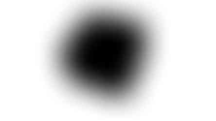
To test the whole projection mapping process for issues I decided to trial a simple scene using the image I created below.

This image is made up of a box cutout, a drinks can cutout, a replacement floor, and some added shadows.
Having some underpaint to account for motion will help sell the effect. If the floor didn't have any colour information behind the box, when the camera moves and reveals that area of the floor Maya will project repeating information that can break the illusion.

Once you've created all the necessary layers, you need to export them each in a lossless colour format, and an alpha mask with white being transparent. .tiff is a good file format choice.
You should end up with a series of images similar to below. I found that painted on shadows are best left on the layer that they're being projected onto, in this case the floor plane.


Projection Mapping in Maya

Once you start a new file in Maya, you need to set your render settings to match the overall dimensions of the image you are projecting from the "Image Size" section. In this case it's 1920x1080.
This aspect ratio will need to match the image you are projecting to avoid any misalignment or scaling issues.
I also found that using a standard image format instead of the Maya file format more useful as you will be able to use the images in other programs
The next step is to create a new camera. Adjust the camera focal length and relevant settings to match if you have any information to work with, or otherwise a best estimate will do.
Now the projected image can be applied to this camera using the "Image Plane" option in the View tab of the camera viewport


Locking off this camera at this point will prevent any accidental movement. We don't need to move this camera again.
The next stage is to add simple geometry to match what you are projecting onto. In this case a floor plane, box and cylinder are required. It's easiest to align these using the other viewport views


Once the geometry is modelled it's time to apply the projected textures. Holding right click on a selected object will allow you to select "Assign New Material" from the drop down list.
Select "Lambert"

Each layer you have created in Photoshop will require it's own material. These materials can each utilise the colour and alpha images created previously.
The menu below will show when you apply a new material to an object in the scene.


The goal is to assign the colour information into the "color" attribute, and the alpha information to the "Transparency" attribute. This is done by selecting the black/white icon to the right which opens a "Create Render Node" dialog box.
Holding right-click on file shows the "Create as projection" option which is used on all the projected textures.

This will create a projection node. The critical settings here are the "Image" which will be used to attach the colour layer.
The "Proj Type" which needs to be set to Perspective.
And the "Link to Camera" which needs to set to the locked off projection camera.
The fit type needs to match your camera settings too.

When you attach the image into the "Image" section of the projection node it is recommended to change the "Filter" value in "Effects" to zero to prevent any white pixels appearing at the border of the projection.
Repeat this process by applying the alpha image to a new projection node from the "Transparency" material attribute of the created Lambert material.
Cycling the viewport shading options (4 and 6) should now show you the projected texture in the viewport.
Below is the scene with the floor, box and can textures applied to simple geometry. You can see how the painted in floor shadow is missing here though. This is because I initially applied the painted shadows to the box and can layers I created.


The same scene, but with the painted shadows baked into the floor texture instead.
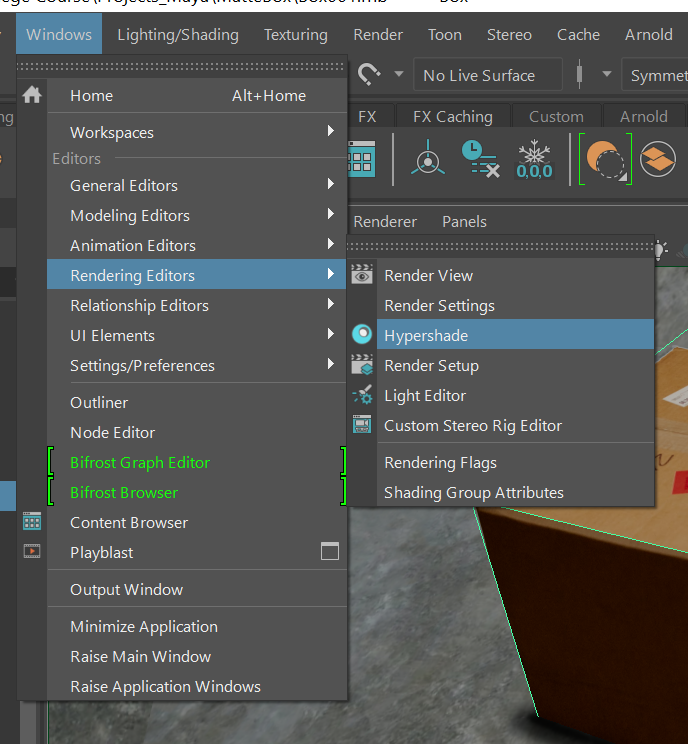
You can view the created textures in nodal form using the Hypershade rendering editor panel shown being accessed here.
One of the issues is that the lighting in Maya doesn't match the levels of the projected image. You can easily use the already projected images to apply Incandescence from the projection node to the "Incandescence" node


One issue with using the image to apply Incandescence to match the lighting is that you can end up with a white area on your geometry - which I thus far have yet to find a solution for.

The below image shows the box unlit with Incandescence showing correctly, but is too dark, and the can lit correctly, but with the excess geometry showing white.

And lastly I duplicated the projection camera to create a new camera on which I can animate without destructively ruining the locked projection.
One of the reasons I added the two objects in the composition like this was that they were overlapping, so there is interaction between the projected layers.
This render from the Maya viewport showcases another issue - clipping of the projected layers.
This is a rendering/viewport bug. To fix the clipping, change the transparency algorithm from "object sorting" to "depth peeling"


Scene now renders with no clipping.
References for Viewport fix


Comments